Astra Application Challenge - Bionic Robot Hand


The Astra Application Challenge was designed to inspire creativity and innovation, encouraging participants to explore the full potential of Astra’s capabilities. Open to developers and innovators alike, the challenge invited participants from our Embedded World 2025: Integrate Cutting-Edge AI Features into Your Embedded Device to build impactful, real-world applications in two exciting categories leveraging Astra's NPU with YOLO models or creating advanced AI assistants integrated with IoT solutions.
🏆Astra Application Challenge Winner : Bionic Robot Hand
Learn more about Astra Application Challenge in the Community section. After a competitive selection process, we’re thrilled to feature GRINN’s outstanding project: Bionic Robot Hand Project, an impressive blend of computer vision, embedded AI, and robotic control. Check out the code in the Grinn GitHub repository.
Edge AI for Gesture Recognition
The Bionic Robot Hand project showcases a hand gesture recognition system that bridges computer vision, embedded AI, and real-time robotic control. Developed to run on Synaptics Astra Machina Board using Astra SL1680 SoC, this demo demonstrates how a compact, power-efficient AI platform can deliver rich interactive experiences using deep learning.
Journey to Real-Time Hand Tracking
This project was designed from the ground up not as a product concept, but as a technical proof of performance and a tangible demonstration of what’s possible when advanced AI processing meets compact, energy-efficient edge computing.
The goal behind this demo goes far beyond entertainment. We aim to inspire engineers, developers, and innovators to explore the broader potential of Edge AI gesture recognition across industries.Imagine medical interfaces that allow surgeons to control equipment touch-free in sterile environments. Think of industrial robots that can respond to human gestures for safer collaboration on factory floors, or smart home systems that understand your intentions with a wave of your hand.Picture in-car gesture controls that let drivers interact with infotainment systems without distraction, or AR/VR platforms where hand motion replaces physical controllers, creating seamless, immersive interaction.
For pose detection, we adapted YOLO‐Pose, a single-stage, heatmap-free pose estimation model originally designed for full-body human pose detection. We fine-tuned it using the HaGRID dataset, a massive collection of real-world hand gesture images.
Designing the Frontend and Backend Pipeline
The project consists of two main components: a backend application that runs the inference and controls the robot hand and a frontend application that displays the results in a kiosk window. The communication between the backend and frontend is done via a WebSocket using an established JSON API.
Frontend
The frontend is intentionally simple – it uses WebSockets to receive JSON updates from the backend, then visualizes the hand landmarks, bounding boxes, countdown timers, and RPS outcomes. It’s a great example of how even basic web technologies can provide compelling interfaces.
Backend
The backend application is written in Python, and uses the SynapRT framework for running the YOLO‐Pose model inference. The main loop of the application is designed to continuously capture images from the camera, perform inference, and control the servomotors of the bionic hand based on the detected gestures.
Under the hood, the main function first spins up both an HTTP server and a WebSocket server. It launches the SynapRT inference pipeline on its own thread, and then enters a tight infinite loop: each cycle it polls the pipeline for new detection results, computes averages of inference time, frame rate, and power usage, feeds the detected hand flexions into the RPS state machine, packages everything into a JSON payload, and broadcasts it over the WebSocket.
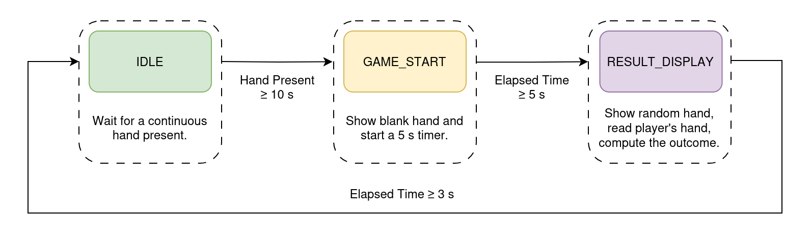
When a hand is detected for more than 10 seconds, the system switches to the rock-paper-scissors game mode. The robot hand stops mirroring the user's hand and instead performs a random gesture. The outcome of the game is determined by comparing the user's gesture with the robot's gesture. After the result is displayed, the system returns to the normal operation mode, where the robot hand mimics the user's hand.
System Hardware Breakdown
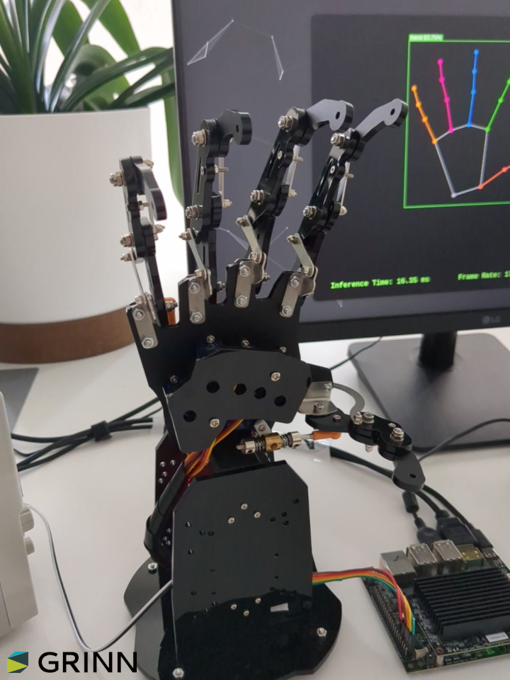
The hardware setup consists of Machina SL1680, with a USB camera, a servomotor controller and a bionic robot hand attached to it.
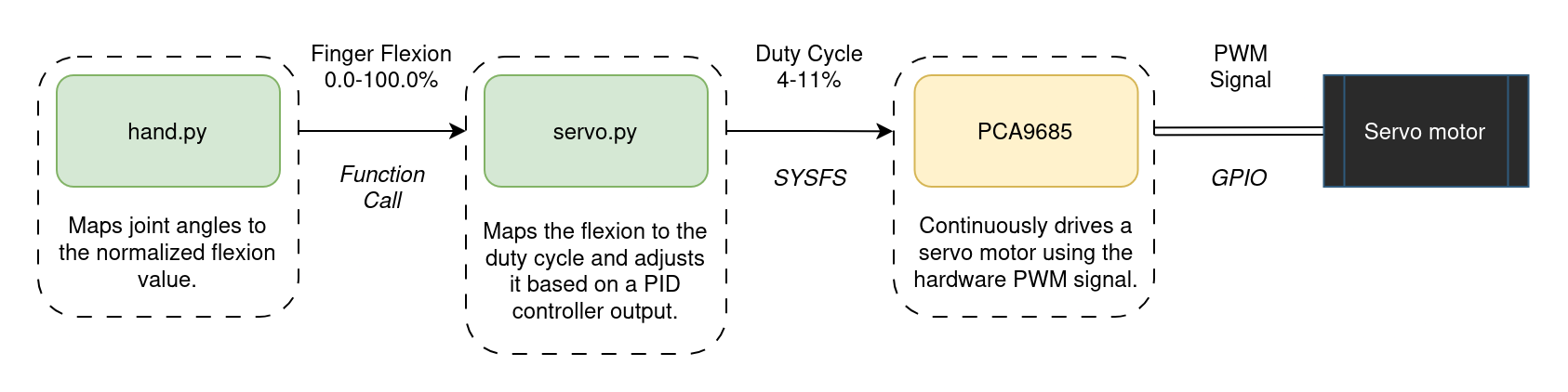
Originally, we tried controlling the servos via GPIO using software PWM. This worked well – until it didn’t. Timing issues caused jitter, especially when multiple servos moved simultaneously under high system load, leading to poor behavior and unpredictable finger movements. This was particularly problematic for the bionic hand, which has multiple servos that need to move in sync to accurately mirror the user's hand gestures. Switching to the PCA9685 hardware PWM controller solved this.
The hardware control has been abstracted into separate modules, with an increasing level of abstraction. The lowest level is the servo.py module, which interacts with the kernel driver of the PCA9685 servomotor controller via the sysfs interface. The next level is the hand.py module, which contains the high-level controllers for the servomotors. It takes raw 3D hand landmarks, filters out low-confidence points, computes inter-joint angles via vector math, smooths those angles over a moving window, normalizes them to 0-100% flexion values, and then either drives the servos to mirror the user's hand in real time or snaps to predefined rock-paper-scissors poses and predicts the player's gesture by matching flexions against pose templates.
The control flow of each finger is shown in the diagram below.
Building with HaGRID: Dataset for Hand Landmark Detection
The HAnd Gesture Recognition Image Dataset provided us with a robust starting point. With over 552,000 images annotated with 21 landmarks per hand and gesture labels across 18 classes, it offered both volume and variety. Images are annotated in COCO format and cover users aged 18 to 65 under varied lighting conditions.
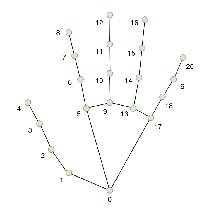
All images are annotated with per-hand bounding boxes [x, y, width, height], 21 hand landmarks [x, y], gesture labels, and user ID. The dataset includes joint landmarks for hand pose detection. Each hand has a total of 21 keypoints. They are annotated as follows:
- Wrist
- Thumb (4 points)
- Index finger (4 points)
- Middle finger (4 points)
- Ring finger (4 points)
- Little finger (4 points)
Adapting YOLO-Pose for Hand Landmark Detection
YOLO‐Pose is a heatmap-free, single-stage extension of the YOLO object detector that performs end-to-end joint detection and 2D multi-person pose estimation in one network. It outputs person bounding boxes along with their associated keypoint coordinates in a single forward pass, eliminating separate heatmap computation and post-processing grouping steps common to two-stage approaches. You can read more about the model in the YOLO-Pose paper.
The YOLO family spans multiple model sizes, each differing in network depth, width and parameter count to balance accuracy against speed. In embedded or resource-constrained environments, the nano and small variants are preferred to ensure real-time inference with minimal compute and memory overhead.
| Model | Depth | Width | Parameters | Use Case |
|---|---|---|---|---|
| YOLO11n-pose (Nano) | Shallowest network – fewer layers | Narrower network – fewer channels per layer | Least number of parameters – lightweight and fast | Suitable for real-time applications on devices with limited compute |
| YOLO11s-pose (Small) | Deeper than YOLO11n-pose – more layers | Wider network – more channels per layer | More parameters – balances speed and accuracy | Ideal for applications requiring a balance between performance and efficiency |
While YOLO-Pose was originally developed for 2D multi-person human pose estimation, here it has been adapted via transfer learning and fine-tuned for hand landmark detection using the HaGRID dataset.
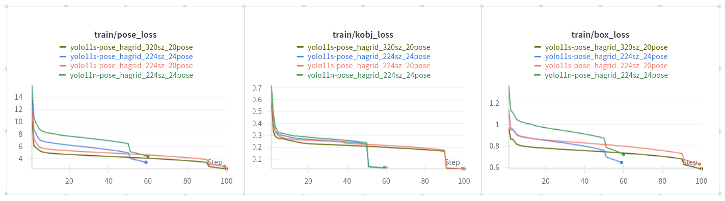
Training and Evaluation
Heatmaps are used to represent the probability distribution of keypoint locations by indicating how likely each pixel is to contain a keypoint. During training the model learns to generate these heatmaps by converting the ground-truth keypoints into target heatmaps and optimizing its parameters to minimize the discrepancy between its predictions and the ground-truth heatmaps.
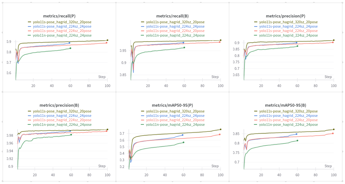
The cls_loss in YOLO11-pose models does not classify keypoints but rather handles the classification of detected objects, similar to detection models. The pose_loss is specifically designed for keypoint localization, ensuring accurate placement of keypoints on the detected objects. The kobj_loss (keypoint objectness loss) balances the confidence of keypoint predictions, helping the model to distinguish between true keypoints and background noise.
For the project, both nano and small models were trained. However, the small version was selected for deployment due to its superior performance in terms of accuracy, while still maintaining a reasonable inference speed.
The models were benchmarked CPU-based inference on the target hardware to establish baseline performance across various input sizes.
| Tensor Size | Load (ms) | Init (ms) | Min (ms) | Median (ms) | Max (ms) | Stddev (ms) | Mean (ms) |
|---|---|---|---|---|---|---|---|
| 640×384 | 162.10 | 609.14 | 558.52 | 574.68 | 590.52 | 9.61 | 574.65 |
| 320×192 | 174.65 | 198.18 | 145.84 | 146.88 | 166.53 | 5.60 | 149.04 |
Lowering the input size to 320×192 resulted in a significant speedup – the model was able to process images in about 150 ms. The 640×384 input size resulted in an average inference time of around 574 ms.
Quantization and Deployment using SyNAP
The model has been exported in ONNX format, and then quantized to a mixed precision format using the synap tool. The whole process is described in detail in the SyNAP documentation. The framework also handles the preprocessing of the input image, which is necessary for the model to work correctly. The preprocessing steps include resizing the input image to a specific size and normalizing the pixel values.
We tested various combinations of input sizes and quantization formats to find the best tradeoff between performance and accuracy. The aspect ratio of the input image was chosen to match the camera resolution.
The following configurations were tested using the synap_cli tool.
| Tensor Size | Quantization | Load (ms) | Init (ms) | Min (ms) | Median (ms) | Max (ms) | Stddev (ms) | Mean (ms) |
|---|---|---|---|---|---|---|---|---|
| 640×384 | int16 | 165.21 | 46.11 | 92.73 | 92.81 | 100.20 | 1.04 | 92.95 |
| 640×384 | mixed uint8 | 86.93 | 23.86 | 51.99 | 52.42 | 59.05 | 0.94 | 52.51 |
| 320×192 | int16 | 144.49 | 42.38 | 20.85 | 20.86 | 27.18 | 0.88 | 21.00 |
| 320×192 | mixed uint8 | 83.73 | 21.41 | 10.08 | 10.22 | 17.47 | 1.01 | 10.41 |
Reducing the input size to 320×192 significantly improved the inference speed. The model was able to process images in about 10 ms, while the 640×384 input size resulted in an average inference time of around 52 ms. The mixed uint8 quantization format also provided a significant speedup compared to the int16 format.
As a result, the 320×192 input size with mixed uint8 quantization was selected for deployment. This configuration provided the best balance between speed and accuracy – making it suitable for real-time applications.
Wrapping Up
This project brings together deep learning, embedded hardware, and real-time interaction in a tangible and playful way. From capturing 3D hand motion to robotic mirroring and gesture-based games, it’s a compelling demonstration of what’s possible on edge AI platforms.
If you're curious about the technical details check out the code in the Grinn GitHub repository. Learn more about Grinn AstraSOM-1680 based on Synaptics' SL1680 processor.