User Guide
Google I/O Edition
This user guide describes the steps involved in booting the Coralboard and running multimodal applications on the Torq AI Engine with Coral NPU in the Synaptics Torq™ AI subsystem. AI Models are compiled on the MLIR-based Synaptics Torq compiler which is part of the open-source Torq toolchain.
For help with any hardware, software, or other issues, please file a support request with Synaptics.
Astra SDK (Linux) features
The Synaptics Coralboard™ Google I/O Edition comes preloaded with a version of Astra SDK (Yocto-project Linux) - specifically Astra SDK v2.2 that was customized by Grinn.
Complete documentation for Astra SDK (including building your own custom image) is located in the Astra SDK documentation.
The preloaded image on Coralboard Google I/O Edition is based on the Astra SDK v2.2 Out-of-Box Experience (OOBE) image, which includes:
- Python3
- IREE runtime for NPU acceleration support
- Multimedia pipelines with GStreamer including Python bindings
- Core services and connectivity
- Graphical desktop with preloaded AI demos (optional, requires display)
The graphical desktop is optional. You can use the board in headless mode or with a display. The Linux kernel and file system is written to on-board eMMC storage.
Synaptics continuously updates the Astra SDK. New releases are available on the Astra SDK releases page.
Official support for the Coralboard Google I/O Edition is in Astra SDK version 2.4, 2.5 but not in 2.6 or later.
You can check the Astra SDK version with the following command.
cat /etc/astra_version
The version will look like this:
scarthgap_6.12_v2.5.0
See Updating Astra SDK (Linux) image below for instructions on flashing a new release to the board.
Python
Example applications are based on Python, although other languages are
supported. Python 3.12.9 is included. Note: Initially, always use the command
python3, not python. Using a virtual environment is recommended - you
can then use python from within the virtual environment.
Enabled features on Coralboard
The preloaded Linux image on Coralboard includes support for:
- Network sharing over USB with Network Control Model (NCM). You can enable network sharing to give the board access to the network through the host machine.
- OV5647 camera (mounted on the included sensor add-on board or separately)
- 7" or 13" Waveshare display
- PDM microphones (on sensor add-on)
- Buzzer / RGB LED (on sensor add-on)
- Wi-Fi card (the AMPAK AP12611_M2 is a compact M.2 2230 card that provides both Wi-Fi 6E and Bluetooth connectivity)
- Ethernet-over-USB adapter
Information and resources
- Astra SDK Linux documentation
- Torq compiler documentation
- Synaptics AI developer zone
- ML example applications
- Astra SDK Linux releases
- Synaptics Coralboard support requests
Set up and connect Coralboard
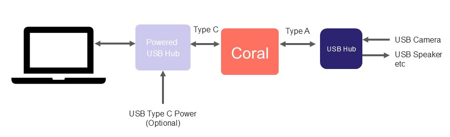
The main power source for the board is delivered through the USB type C connector. The USB type C port also enables communication with a host machine. You can connect USB peripherals to the type A port on the Coralboard, using a hub if necessary. Be mindful of the amount of power required by USB peripherals (hardware limit of approximately 0.6A @ 5V, 3W). You can use powered hubs for peace of mind.
Unbox and assemble hardware
See Getting started.
Connect power and peripherals
- Connect your USB peripherals (such as a camera) to the USB Type-A port on the Coralboard.
- Use a powered USB hub if you are connecting multiple peripherals to ensure you have sufficient power.
- Provide main power to the board by plugging a cable into the USB Type-C port. Connect the other end of this USB Type-C cable to your host machine to enable communication.
Select boot mode
Coralboard includes a physical switch that determines the location of the software boot image. The image can be loaded from the eMMC memory (default) or from an SD card (optional). Ensure the switch is set to the "1" position.
- 1 / OFF: eMMC boot (default)
- 0 / ON: SD card boot
Attach Wi-Fi/Bluetooth module (optional)
The Coralboard supports a specific Wi-Fi/Bluetooth module that is designed for Synaptics by Ampak: the AP12611_M2 is a compact M.2 2230 card that provides both Wi-Fi 6E and Bluetooth connectivity. See M.2 card.
To attach the Wi-Fi/Bluetooth module:
- Slide the AMPAK AP12611_M2 module into the M.2 connector on the board and secure it with an M.2 screw.
- Attach the antenna to the module.
Follow this guide in the Astra SDK docs to enable Wi-Fi and connect to a network.
Bluetooth radio can be controlled with bluetoothctl. Follow this guide to connect
to Bluetooth devices.
Attach MIPI DSI display (optional)
The Astra SDK for Synaptics Coralboard Google I/O Edition supports 7", 10", and 13" MIPI DSI touchscreen displays from Waveshare. See Touchscreen displays below for the tested display models and purchase links.
To connect a 7" display:
-
First disconnect the USB-C power cable.
-
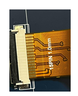
Connect the included ribbon cable to the back of your display by flipping the black strip up, inserting the ribbon with the metal connections facing up, and pushing the black strip down.
-
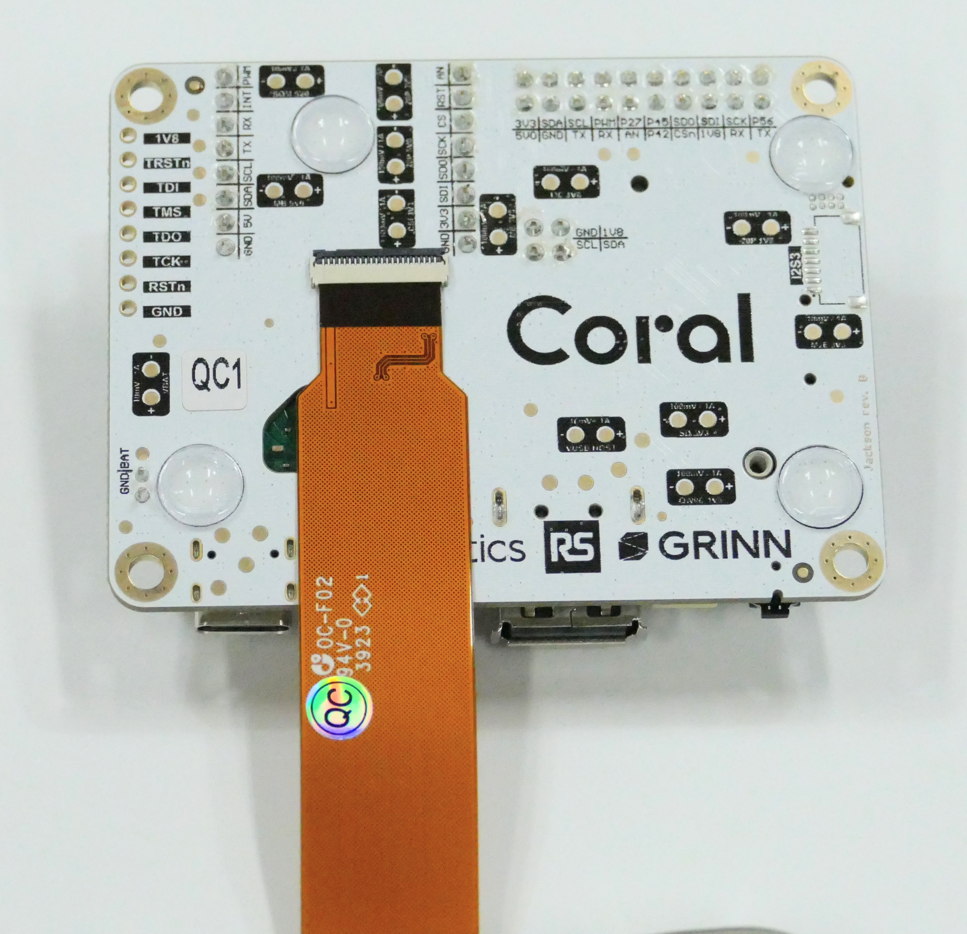
Connect the other end of the ribbon cable to the Coralboard by flipping the black strip up, inserting the ribbon with the metal connections facing down, and locking the strip down.
-
Connect a power supply to the display.
You can connect to the 5V and GND on the Coralboard header, however it is recommended to power the display from a separate 5V and GND source.
Note that a 13.3" display has its own USB-C port to power the display.
-
Reconnect the USB cable.
-
Enable the device tree overlay to support the display (see next section).
Enable overlays in U-boot
Different naming conventions exist between the following Linux image versions:
- Custom image by Grinn (default)
- Official images by Synaptics (Astra SDK v2.4 & v2.5)
Follow the next section for details.
Support for the following items are enabled by applying device tree overlays in the U-boot bootloader terminal:
- Touchscreen displays
- Sensor add-on board
To apply an overlay, first connect to the U-boot terminal.
- Attach to the serial (use the built-in USB-to-Serial circuit on the sensor add-on or using a separate USB-to-Serial adapter plugged into the I/O header UART signals - RX, TX, GND)
- Press reset on the board. Press enter several times quickly to halt the
processor from booting into Linux. You should get to a U-boot command line
with a
=>prompt. - Follow these commands to set and save the overlays.
Overlay commands for default Linux image (Grinn version)
For 7" display & Sensor add-on
=> setenv dtbo "grinn-astra-261x-coral-ws-panel-overlay.dtbo grinn-astra-261x-coral-hat-overlay.dtbo"
=> saveenv
For 13" display & Sensor add-on
=> setenv dtbo "grinn-astra-261x-coral-ws-1080p-panel-overlay.dtbo grinn-astra-261x-coral-hat-overlay.dtbo"
=> saveenv
Overlay commands for Astra SDK v2.5
For 7" display & Sensor add-on
Note that the 7" display is already supported by default. Applying a non existent overlay can cause problems processing other overlays.
=> setenv dtbo "sl2619-coralboard-hat-overlay.dtbo"
=> saveenv
For 13" display & Sensor add-on
=> setenv dtbo "sl2619-coralboard-ws-1080p-panel-overlay.dtbo sl2619-coralboard-hat-overlay.dtbo"
=> saveenv
To see a list of included overlay files, check the /boot directory after booting up Linux.
ls /boot
For more information, see the Waveshare Panel Configuration Guide in the Astra SDK docs.
Connect to a terminal
There are two ways to get a Linux command-line prompt.
Method 1 – ADB (recommended)
Download Android SDK Platform-Tools. See the documentation for ADB.
Use this command to open a shell:
adb shell
You can also send and receive files with ADB (see below).
Method 2 – USB serial
You can use a USB-to-serial adapter to connect to a UART port to access U-boot when the system is booting up, as well as the Linux terminal. The USB-to-Serial adapter will enumerate on your machine as a serial device (virtual com port). See additional information here.
Use the sensor add-on
If you are using the sensor add-on board (plugged into the Coralboard), you can use its built-in USB to serial adapter.
Note: You may need to install a driver on your host machine for this connection to work. The CP210x USB-to-UART Bridge VCP driver is available from Silicon Labs.
On Windows:
Install the driver. Use any serial terminal program: Putty, Tera Term, etc. The Coralboard will show up as a new COM port.
On macOS:
For macOS you can use the screen command to connect to the serial port; no
driver required.
# Find out what the device is named
ls /dev/cu.usb*
screen /dev/cu.usbserial-xyz 115200
On Linux:
The cp2101 driver is included in most distributions. You may need to install
screen or another terminal emulator of your choice.
# Find all ttyACM devices
ls /dev/ttyACM*
screen /dev/ttyACM0 115200
Connect to a network over USB
You can grant the Coralboard access to your machine's network over the USB interface. Note that this feature may be blocked by your local IT policies on managed systems.
On Windows 11:
- Open the Start menu and search for Network Connections. Click to open it.
- Right-click your active internet connection and select Properties.
- Go to the Sharing tab.
- Check Allow other network users to connect through this computer's Internet connection.
- In the Home networking connection dropdown, select the UsbNcm Host Device.
Note that on Windows 11, ICS (Internet Connection Sharing) on the host machine does not work after rebooting. In order to start it again, you must disable and then re-enable ICS after reboot.
On macOS:
ICS (Internet Connection Sharing) can be set up on macOS with these actions:
- Connect Device: Connect the Coralboard to the Mac via USB.
- Locate Sharing: Open System Settings > General > Sharing.
- Configure Sharing: Share your connection from: Choose your internet source (e.g., Wi-Fi, Thunderbolt Ethernet).
- To devices using: Select the USB adapter or the specific device identifier corresponding to the NCM device.
- Enable Internet Sharing: Toggle the switch turn on. The Mac will now serve as a DHCP server to the connected USB device.
The IP address scheme for NCM is configurable on the device, allowing you to use either DHCP (recommended) or a static IP configuration. In DHCP mode, the Coralboard gets an IP from the host machine and is able to communicate with the outside network as one would expect.
Using sensor add-on board features
If you have the sensor add-on plugged into your Coralboard, you can use the following features.
Some useful commands are shown to test the features on the command line. You can also use these features in Python applications. See the example applications for more information.
PDM microphones
The microphones are available as an ALSA audio input device.
To list available audio input devices, use this command - look for card: x to identify the card / device number.
arecord -l
To record audio, use this command (with the format -D hw:<card>,0):
# PDM mics (default)
arecord -D hw:0,0 -f S32_LE -r 48000 -c 2 -d 5 /home/root/pdm_mic_test.wav
Note: To use an USB microphone, just change the device number (based on results of arecord -l).
aplay -l    # find the card/device number for your speaker
gst-launch-1.0 -e alsasrc device=hw:0,0 ! audioconvert ! audio/x-raw,format=S16LE,rate=48000,channels=2 ! alsasink device=hw:<card>,0 sync=false
Buzzer control
The Grinn version used libgpiod v1 for GPIO control. The Astra SDK v2.5 uses libgpiod v2.
To test the buzzer, use these commands:
Grinn version:
gpioset 'gpiofind BUZZERn'=1 # OFF
gpioset 'gpiofind BUZZERn'=0 # ON
Astra SDK v2.5:
gpioset -t0 BUZZERn=1 # OFF
gpioset -t0 BUZZERn=0 # ON
LED controls
LED controls follow standard Linux mechanisms. They can be found in the
/sys/class/leds/ directory
Enable commands:
echo 255 > /sys/class/leds/red\:status/brightness
echo 255 > /sys/class/leds/green\:status/brightness
echo 255 > /sys/class/leds/blue\:status/brightness
Disable commands:
echo 0 > /sys/class/leds/red\:status/brightness
echo 0 > /sys/class/leds/green\:status/brightness
echo 0 > /sys/class/leds/blue\:status/brightness
LED dimming is not supported, so any value >= 1 enables them fully.
USB Speakers
Plug in a USB speaker to play audio.
Check audio playback device details with this command - look for card: x to identify the card / device number.
aplay -l
To play a file, use this command (with the format -D hw:<card>,0):
aplay -D hw:<card>,0 pdm_test.wav
Transferring files
There are two ways to transfer files to and from the Coralboard.
Method 1 – ADB
You can push and pull files from your machine with ADB.
To push a file to the Coralboard home directory: adb push file /home/root/
To get a file from the home directory: adb pull /home/root/<file> <destination-path>
Method 2 – SCP
You can use SCP if you are connected to a network and know the Coralboard's IP address.
To push a file to the Coralboard home directory:
scp -r <file> root@<board-ip>:/home/root/
To get a file from the home directory:
scp root@<board-ip>:/home/root/<file> <destination-path>
USB drive file system
To create a mount point directory:
mkdir -p /mnt/usb
Mount a Fat32 formatted drive:
mount -t vfat /dev/sda1 /mnt/usb
Mount an ext4 formatted drive:
mount -t ext4 /dev/sda1 /mnt/usb
Unmount
umount /mnt/usb
SD card file system
To create a mount point:
mkdir -p /mnt/sd
Mount the drive:
mount /dev/mmcblk2p1 /mnt/sd
Unmount:
umount /mnt/sd
Updating Astra SDK (Linux) image
The Google I/O Edition Coralboards are preloaded (flashed) with a version of the Synaptics Astra SDK v2.2 that is customized by Grinn.
Synaptics continuously updates the Astra SDK. New releases are available on the Astra SDK releases page.
Official Astra SDK support for the Coralboard Google I/O edition was included in v2.4 and v2.5.
The correct boot source must be selected - only eMMC is supported (S3 switch in the "1" position) currently.
You can update the Linux SDK image in two ways.
Download Astra SDK release v2.5
Under sl2619, locate the Coralboard OOBE image download script.
- Image for sl2619_coralboard_oobe_scarthgap [Windows] [MAC / Linux]
Choose the right script depending on your host machine.
Run the script to download the release zip file (sl2619_coralboard_oobe_scarthgap_6.12_v2.5.0.zip)
Method 1 – USB boot script
In the Astra SDK docs, check out the section Updating Astra Software
Depending on your host machine, you may need to update your USB drivers.
Download the usb-tool repository.
Enter the usb-tool directory.
Extract the release zip file here. The folder should be named eMMCimg.
Run the update_emmc script to kick off the update process. The specific script file depends on your host machine.
To enter USB download mode, press and hold the USER button and click the RESET button. The download process should start. It will take a few minutes to complete.
Method 2 – U-boot with USB flash drive (or SD card)
This method is described in the Astra SDK docs at Flashing eMMC Images from a USB Drive.
It requires USB-to-Serial adapter.
Download the release zip file and extract it onto the USB drive. Plug the drive into the USB Type-A connector on the Coralboard.
Connect to U-boot as described above. While connected to the serial port, press the reset button.
Then press any key several times to interrupt the booting process. You should then get to the U-boot prompt =>.
Reset the USB to gain access to the devices:
=> usb reset
List files in the USB drive:
=> ls usb 0:1 /
=> usb2emmc <folder_name>
folder_name in this case is eMMCimg but for custom Astra SDK Yocto builds it is SYNAIMG.
Wait until it completes.
To use an SD card instead of USB drive, change the command to:
=> sd2emmc <folder_name>
Connecting to an external USB-to-serial adapter
If you are not using the sensor add-on board, you can still access the system console with any 3.3V TTL serial adapter.
Be sure that you have an adapter that is compatible with your system. One example of these type of adapters is the Adafruit USB to TTL Serial Cable which has 3.3V I/O levels.
Attach the serial port wires as shown, taking care to connect the TX and RX pins correctly for the adapter. Plug the wires onto the GND, TX, and RX pins of the 20-pin GPIO header on the Coralboard:
| Pin | Function |
|---|---|
| 4 | GND |
| 6 (output-only) | SM_URT0_TXD |
| 8 (input-only) | SM_URT0_RXD |
After making these connections, open the connection on your machine.
Supported components and peripherals
The items listed have been tested with Coralboard.
Touchscreen displays
Wi-Fi module
USB peripherals
- Cameras
- Speakers
- Hubs
USB-to-serial adapters
- Example: USB to TTL Serial Cable